Aug 20, 2024
Why 3D Scan Data is Typically STL Instead of STEP
When working with 3D scanning, one of the first things you'll encounter is that the output is almost always an STL file rather than a STEP file. This distinction might seem trivial at first, but it’s rooted in the fundamental differences between these two file formats and the nature of 3D scanning technology.
Understanding STL and STEP Files
STL (Stereolithography) is a file format native to the 3D printing industry, representing the surface geometry of a 3D object without any color, texture, or other attributes. It’s essentially a collection of triangles (facets) that approximate the shape of the object’s surface. Each triangle is defined by the coordinates of its three vertices, making STL a straightforward, widely supported format for representing 3D shapes.
STEP (Standard for the Exchange of Product Data), on the other hand, is a CAD (Computer-Aided Design) file format used for sharing detailed product models across different software platforms. STEP files store not just the surface geometry but also the mathematical representation of curves, surfaces, and even assembly hierarchy and relationships. This makes STEP ideal for design and engineering, where precision and the ability to modify the model are crucial.
Why STL for 3D Scanning?
-
Surface Representation vs. Solid Modeling: 3D scanners capture the physical surface of an object by collecting a cloud of points that represent its shape. This data is inherently a mesh of vertices forming triangles, which is exactly what STL files are designed to store. Since 3D scanning focuses on replicating the external geometry rather than the internal features or design intent of the object, STL is the most natural fit.
-
Data Complexity: STEP files are excellent for conveying complex design data, including exact geometry and assembly instructions. However, 3D scanning doesn’t capture this level of detail. Scanners provide a high-density point cloud or mesh that represents the outer surface of an object. Converting this raw data into a STEP file would require reverse engineering to create solid models from the mesh, a process that is not only complex but also unnecessary for many applications.
-
File Size and Processing: STL files are often smaller and easier to process than STEP files because they don’t include the additional data that comes with solid modeling. This makes them faster to generate, transfer, and work with, especially in applications where the scanned object’s surface detail is more critical than its internal features.
-
Compatibility: STL is the de facto standard in 3D printing and is supported by virtually every 3D printer and modeling software. Since one of the most common uses of 3D scan data is to create models for 3D printing, using STL files ensures broad compatibility and smooth workflows from scanning to printing.
The Challenge of Converting STL to STEP
While STL files are perfect for representing surface geometry, they lack the parametric information necessary for CAD modeling, which STEP files provide. Converting STL to STEP is far from a straightforward task—it’s a labor-intensive process that often requires specialized software and significant engineering expertise.
The conversion process typically involves several steps:
-
Mesh Repair: Since STL files are purely mesh-based, any errors or inconsistencies in the mesh (like holes, non-manifold edges, or intersecting triangles) need to be corrected before conversion.
-
Surface Reconstruction: Engineers must recreate the surfaces of the scanned object from the mesh data. This involves interpreting the mesh to define smooth curves and surfaces, which can be particularly challenging with complex geometries or when the mesh quality is poor.
-
Solid Modeling: Once the surfaces are reconstructed, the next step is to convert these surfaces into a solid model. This step is crucial for creating a usable CAD model but requires a deep understanding of the object’s design intent, which the original scan data doesn’t provide.
-
Feature Recognition: Finally, to make the STEP file editable, engineers often need to manually add features like holes, fillets, and chamfers, which are essential for further design modifications.
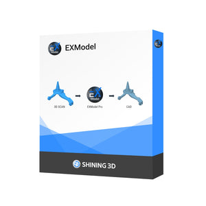
This process is time-consuming and often requires advanced software tools, such as QuickSurface, EXModel or Geomagic Design X, and experienced engineers who can interpret and manipulate the data effectively. For complex parts, this process can take days or even weeks, depending on the level of detail and the intended use of the STEP file.
Conclusion
The choice of STL over STEP for 3D scan data is driven by the fundamental differences in what these file formats are designed to achieve. STL’s simplicity and suitability for surface geometry make it ideal for the kind of data produced by 3D scanners. However, when a precise, editable CAD model is needed, converting an STL to a STEP file requires significant engineering labor and specialized software, making it a complex and costly process. Understanding these distinctions helps ensure that the right tools are used for the right jobs, optimizing workflows and results in the world of 3D scanning and beyond.


